


Background
Bombardment of a material with high energy X-rays causes emission of secondary X-rays that are characteristic to the elemental composition of the material. The emission is called X-ray fluorescence (XRF), which is a widely spread technique for material characterization. Most of the XRF instruments are stand alone spectrometers for bulk measurements. Applications range from thin film analysis to elemental identification and quantification.
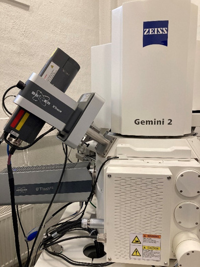
So called µXRF is an XRF spectrometer mounted on a scanning electron microscope (SEM) (Figure 1), allowing identification and mapping of elements with improved spatial resolution (~10 µm) compared to traditional XRF instruments.
The sample was a zinc-coated steel specimen with two organic coating layers (polyurethane). The sample was exposed in humid salt environment to induce blistering.
The measurements were performed on a Zeiss Gemini 2 SEM instrument equipped with a Bruker XTrace micro-XRF. Cross-sectioning was performed with an ion beam mill (BIB, Gatan), and conventional SEM/EDS was used for element mapping of the cross sections. In addition, Raman measurements (Renishaw InVia Qontor) on the cross-section was performed.
Results
µXRF measurement
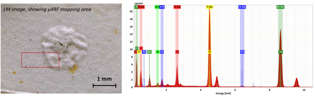
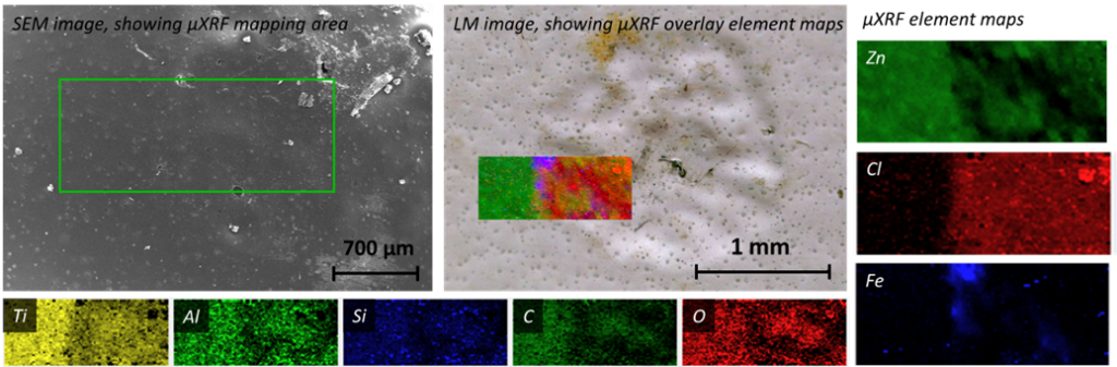
Figure 1, left, shows a light microscopy image of a blister with µXRF measurement area indicated. A µXRF measurement spectrum (Fig. 1, right) shows presence of elements derived from zinc-coated steel (Zn, Fe) as well as elements originating in the coating. Ti comes from titanium oxide (pigment), Al and Si refer to ion-exchanged silica (corrosion inhibitors in primer), as well as silica matting agents. Carbon is related to the polyurethane coating matrix. Oxygen is widely available in inorganic pigments (like TiO2). In addition to these elements, also chlorine was detected. Chlorine element map (Fig. 3) shows predominant presence of Cl within the blister area. Furthermore, zinc signal (coming from the zinc coating beneath the organic coating) is disrupted at the blister area, and iron is locally visible. The findings based on the µXRF measurement indicate Cl-induced metal corrosion as the root cause for blister formation.
SEM/EDS measurement from cross-section
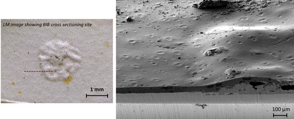
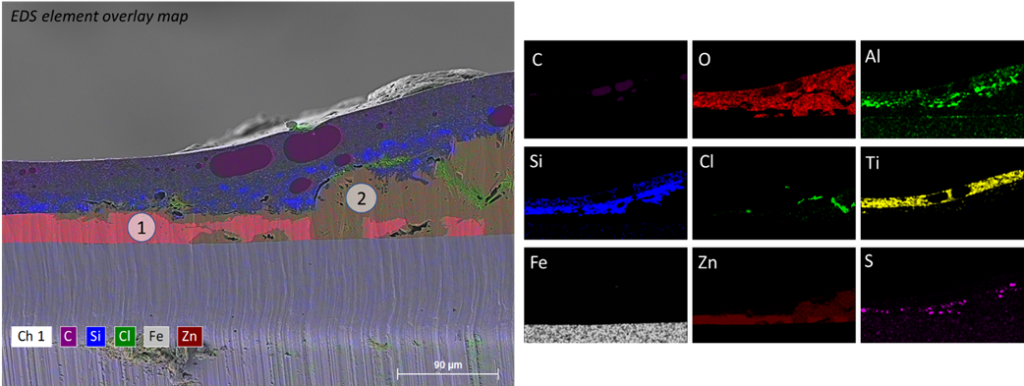
A closer look at the blister composition was taken with SEM/EDS from a cross-section produced by ion beam milling. In Figure 4 (left), the dotted line shows the cross-section site. SEM imaging of a tilted sample (to 25º) shows the edge of the blister with (presumably) metal corrosion products under the coating at the blistering area. The result was confirmed by EDS measurement (Fig. 5): the zinc coating is locally dissolved all the way to the steel core. Metallic zinc (“1”) with intact coating layers is visible outside the blister, while oxidized zinc (“2”) prevails under the blister. Strong local concentrations of chlorine were observed within the corrosion products.
Raman measurement
Corrosion product composition was studied with confocal Raman. Spot measurement (the red circle shown in Fig. 6, upper left) verified the presence of Zn5(OH)8Cl2·H2O, which is a typical zinc corrosion product in humid chlorine environments.
Figure 6. Raman spot measurement from the corrosion products within the blister.
Conclusions
Blistering of zinc-coated steel with two-layer polyurethane coating was studied with µXRF, SEM/EDS and Raman. The techniques confirmed the presence of chlorine as the main driver for blistering. Under the blister, the zinc coating was locally oxidized all the way to the steel resulting in abundant formation of zinc chloride hydroxide monohydrate formation.
Cross-sectioning, followed by SEM/EDS and Raman investigation, is a powerful combination to study blister root causes. However, the sample preparation and measurement procedures are time consuming and a risk of neglecting minute features within the blisters exist since only a small cross-sectional area is studied.
µXRF offers several advantages for blister studies:
- Improved spatial resolution (~10 µm) compared to conventional XRF instruments
- Possibility to perform µXRF measurements from sample sites chosen with SEM imaging
- Possibility to do parallel SEM/EDS and µXRF determinations
- No need to coat the samples
- Possibility to measure underlaying layers
- Non-destructive
- Better sensitivity to light elements than conventional XRF
- Operated in a vacuum condition
- Thinner window than in conventional XRF (thick window prevents low-energy X-rays from reaching the detector)
Keywords: Coating, micro-XRF, Raman, SEM, EDS, blistering